Thursday, September 22, 2011

Feedback from a blog visitor


 In electronics we usually encounter feedback circuit; the purpose of feedback circuit is basically to couple a sample of the output signal back to the input of the circuit. This signal is analyzed and compared with what is expected.

If the sampled signal(Voltage) is less the expected then the control circuit will cause the switch(e.g.transistor) to move faster in order to increase the output monitored source and vice versa
In real life scenario feedback is also very important, for example as a blogger it is very important for the followers to take some time once in a while to let the host know if what we are giving is high or low value contents.

This will guide us to respond accordingly and in doing so improve on what need to be improved and suppress what is not relevant to you as consumers…one of the best way to let us know how we are fairing as bloggers is by dropping a line or two on the comments box.

Blogging is generally a very social community and therefore those who are active in it often get recognized and this can lead to more visitors to your blog or even more opportunities may come knocking your doors.
 Below you can see a comment dropped by a Mr. JG Manza after reading this article on Akira Television dead.


Another very important form of feedback is Guest posting, once in a while consider writing an article for other websites and by so doing you will get an idea of the quality of your content if you are getting started in this road of electronics.

I never knew I am good at writing electronics articles until the time I was given an opportunity by Mr Jestine Yong of Best electronics articles to write an article in his monthly electronics repair newsletter and from the feedback I got from the readers really gave me more confidence to move on writing more and more, eventually I wrote my first eBook on CRT television repaircourse.

All the best guys

See you on the other side.

Saturday, September 10, 2011

Akira Television 21 Inch dead


Roger: sir good day,,,,now I’m repairing a 21 inch,tv,akira,,,,the power regulator ic is down,,,so i replace,,,,there is also a ceramic disc cap rated 222k is burnt already at secondary side, beside output diode, so i replace,,,by the way the fuse have burnt also,,,,so i power the set using light bulb,,,when i plug i noticed the front led not lighted,,,,, what the area I’m going to check sir,,,maybe the micro not power also,bcos,,no 5volts,,,,, by the way this tv is using power ic,,,str g6653,,,even there is no 5volts ,I try to sw.on the set,,and i can do voltage testing,,,the main cap is 300v,,,pin 1 of ic is 300v also,,,,pin4 is about 14to 16v,,,,pls,advise me sir,,thanks,,roger

Humphrey: Any voltage on the secondary side of the power supply?

Roger: sir, good day,,,i continue checking at primary side, I bump to a resistor rated .15 ohms,,,its reads 18k ohms,,,so i check the link of this low ohms resistor,,,it connected to pin 2 of str g6653,,,it is a current sense resistor,,,that turn to high ohms,,,i think this is cause why the power supply and also front led not functioning,,,,,am i correct sir?,,,now im preparing to install a new low ohms resistor,,rated 0.47ohms,,,,,because    0.15-ohms is not available,,,,maybe this tv is start working,,,,after i replace total of 5 components,,,,,,by the way sir thanks,,,,,,i let you know ,after i fix this tv,,,,god bless,,,roger

Humphrey: 0.47 ohms is still quite high for current sense resistor...use three 0.47 ohms resistors connected in parallel to get 0.16 ohms for this circuit.

 Roger: ok,sir ill do that your good advise,,,,i will make 3 ,,,,,,,0.47ohms resistor in parallel,,,,thanks

Roger: sir good day,,,,after i replace a e-caps at the vcc rail of str g6653,,,when i sw.on the front led has come on now,,,,but i notice the light bulb is having intense light,,,,so i check the voltage at the secondary diodes,,,all are ok,,,but the B-positive is low,,,i disconnect the degauss coil,,,,check again the voltage at B-positive its reads 112v,,,so i confirm the posistor is already short,,,,Because  i check the degauss coil is ok,,,,now,,,all the voltage output at secondary is present,,,,but the tv does not sw.on,,,,,the front led is ok also,,,,,the micro is already powered,,,,but why the tv cant sw.on ?   so i check the condition of fbt,,,primary winding is ok,,,,i powered again the set and check the fbt secondary voltages,,,the 185v reads only 112v,,,,,,the screen voltages reads 3.2v,,,,,the other fbt output no readout,,,,,so why this happen sir think the fbt is already gone also sir? Even though the primary winding of fbt is ok? You know sir? I learn a lot in this trouble-shooting,,,pls.advise me sir,,thanks,,roger

               
Humphrey: I don’t think the fly back has a problem, I suspect the horizontal drive circuit, read your book chap 10 for more details on testing and troubleshooting this circuit.
The Voltage of 112volts at the output of the FBT is same as the 112volts b+ voltage because the fly back is not switching. So this leads us to suspect a problem with the drive circuit. For example any voltage at the collector of the drive transistor? How much?
Check that and come back to me please.

Roger: sir good day,,,,,yes is true that the output voltages the same,,,,,,112v,,,,now my mind is thinking so much,,,,I  have read again the book at chapter 10,,,,,i think my assumption is correct,,,to double check the horizontal drive circuit,,,,,,so i confirm to you sir about your advise,,,,,,sir you know you’re a nice guru for me,,,,,so i study hard for this field,,,,,especially CRT TV repair,,,,,big thanks for your advise sir,,,,,i let you what the progress of repair
               
Roger: sir good day,,, I check the horizontal drive circuit,,,,i power on the tv,,and test the voltage at collector of h-drive transistor it reads 112v,i trace the line is coming from the b-positive line,,,pass the two 10k resistor in parallel,,,,i check the pulses at the base ,,i find dry joints,,,,so i re-solder the area of h-drive and the pulses is ok,,, ,,,,now the set is totally power on,,,,sir you know I have so much learn about your advises for me,,,,i have so many things in trouble shooting that i have learn,,,,dos and don't,,,,procedures,,,the principles that I learn in your book is giving me a inspiration to continue learning this field,,,now my confidence is simply increasing,,,,,b-cous of your support sir,,,,

Friday, September 9, 2011

Leader pattern generator (model LCG 398-B) repaired


Recently during some test on a CRT Television I found out my pattern generator is not working after many years of service. The switches on the panel were broken and also no signal was coming out of the equipment.
I opened up the machine and upon keep observation I noticed numerous dry joint and I re-soldered them and also replaced the broken keys and the machine came back to life.


This report is brought to you by Mr. Beh.
An electronics repairer based at Tehran in Iran
If you want to learn about this equipment and what it’s capable of doing click on the like below


Friday, September 2, 2011

How to make up any value of resistor for replacement if you can’t get the exact value


On your line of duty as a technician in electronics sometimes you may come across a resistor burnt or has changed its original value and being one of the cheapest component in the market you visit your nearest electronics shop but alas, they can’t get the exact resistor value you are looking for.


I have in mind the example of the current sense resistor which is found in almost all switch mode power supply. Current sense resistors are usually low ohm and very precise and therefore a small change in its original value (usually upwards) can cause the whole power supply to appear dead.


In this lesson I am going to talk a bit on how you can make up any value of resistor you need for replacement in case you can’t get the exact value. In order to accomplish this mission we are going to use some characteristic of resistors when connected in series and in parallel.


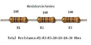
If resistors are connected in series then their individual resistance are added together to get the total resistance. See picture below.


If resistors are connected in parallel their total resistance is always less than the smallest resistor value in the association. In the example below we have two one(1 Ohm) resistors in parallel. If the resistance value is the same in parallel association then the formula is simple. Just divide the value of one resistor by the number of resistors.

From the above picture we have the value of the resistor is One(1 Ohm), to get the total value of resistance in parallel just divide the 1 ohm by the number of resistors two(2) and the value is ½ or 0.5 ohms.


As you can see the total resistance value is less than the smallest value resistor (in our case one (1 ohm). Therefore if you wanted to get half ohm resistor there you are.


So next time you encounter problem of getting a certain resistor value now you know how to go round this problem.


All the best Guys

See you in the next class