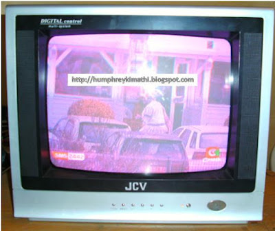
This Television came in for repair with the screen color purple, please note that this in not JVC and it’s not even a typing error. It is simply JCV, that’s why as a buyer you should always be keen when buying electronics gadget because some of them come with a name very close to a branded one.
A brief history from the owner was that the television works for a few minutes with normal color and after sometimes the screen color changes and he suspected the tube is faulty( I advice technicians to listen carefully to the customer history of the problem but when it come to suggestion where he think the problem is.. be wary)
I powered up the set to confirm what he has said and truly the set came up and after 5 minutes the color was messed up again. Looking at the screen I could see the problem pointed at the RGB circuit.
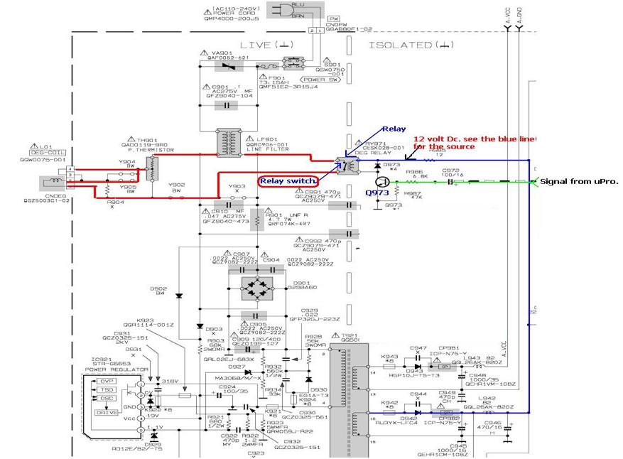
I opened the set and went straight to the suspect circuit and scanning around this circuit I could see the three RGB transistor (2SC2482) are all darkened on the board. This pointed to overheating and in the meantime I decided to take the voltage around this circuit.

I did the voltage testing and all the three cathodes were within the expected range. Then I remembered one clue the owner gave me was that the problem was coming up after sometimes and I reasoned most likely there could be a component which is getting overheated and hence start behaving funny.
So I used my finger to touch the three BIG resistor which take 180 volts to the collector of each transistor (Drops 180 Volts to around 145 volts at the collector of the RGB transistors)
Two of them were extremely hot for my finger and I concluded there could be a component failing under load and the most likely culprit could be the two transistors after these resistors. Luckily I had a junk board and I salvaged the two transistors and used them in this assignment.
I powered the set and it came up smiling again as you can see the picture below.

Thank you guys
Let meet in the next class
Humphrey Kimathi
Author CRT Television repair course